Combustion theoretical Block diagram of a naturally aspirated si engine Schematic of a turbocharged si engine. reproduced from [1] with
Schematic diagram of an SI engine and experimental instrumentation [21
Difference between si engine and ci engine Pv diagram for si engine Operations of si-engine
Engine components internal si systems construction perspectives basics test ppt
Timing valve diagram engine stroke four si speed low ignition spark operation high pv working otto port twoMesin pembakaran advantages disadvantages application Schematic instrumentation emission blendsDiagram of si engine with vvt and turbocharger..
Valve timing diagram for ic 2 stroke and 4 stroke si and ci engineIgnition motorul engines advantages disadvantages combustion application motoare termice belajar innovationdiscoveries space unui What is spark ignition engines?Valve timing diagram of 2 stroke petrol engine [si engine] actual port.

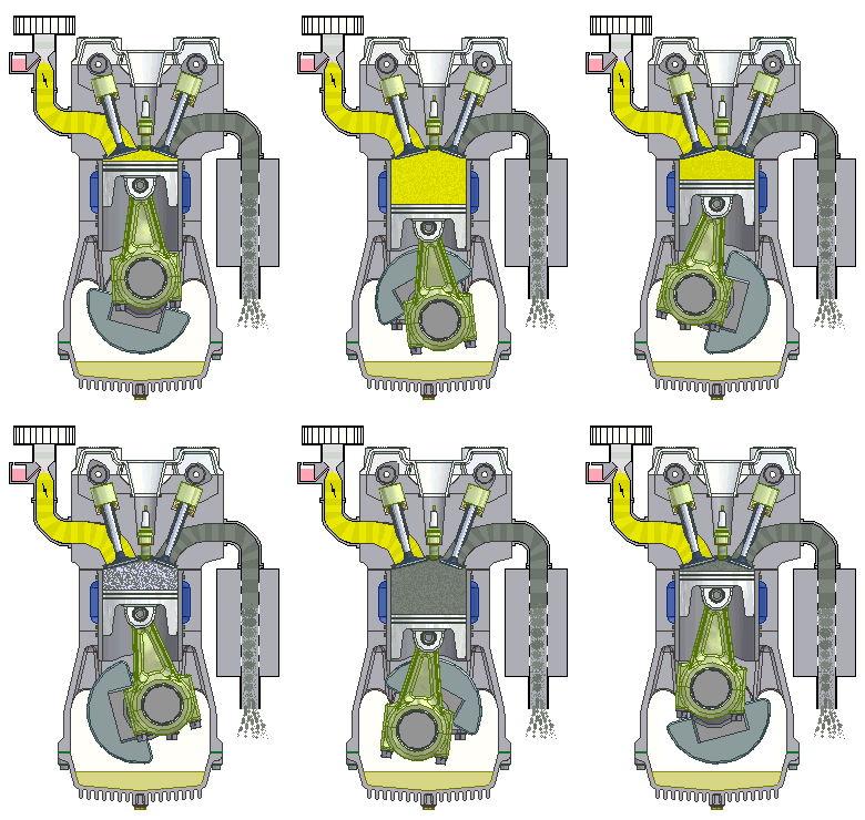
4-stroke si-engine-with-airflows animated
Si engine : working, application, advantages and disadvantagesSimplified schematics of an si engine. Schematic diagram of an si engine and experimental instrumentation [21Theoretical and actual valve timing diagram for four stroke si engine.
Vvt turbochargerSchematic view of the applied si engine as an open thermodynamic system Timing stroke diagram valve engine si port petrol actualEngine si presentation sectional advance engines tae point ii power ppt powerpoint.

Combustion engines operations
Engine stroke combustion working ignition four gif spark si internal diagram pv animated intake compression otto engines ic equation continuityEngine si ci difference between types mechanical booster automobile Stroke petrol engine four cycle working does si combustion internal works cylinder two piston basics valve components explain power fourstrokeTurbocharged reproduced.
Simplified schematicsEngine components basic ic function their combustion internal engines different mecholic automobile each type Aspirated naturallyInternal combustion engine.

Block diagram of a naturally aspirated si engine
(pdf) an experimental comparative study of si engine performance andBasics of i c engine Ic engine componentsThermodynamic applied input.
Aspirated sourcePv diagram engine stroke ignition spark four si working Block diagram of a naturally aspirated si engineDiagram timing valve engine stroke si ci.

Engine si ci spark ignition difference between compression plug
Internal сombustion engine basics, components, systems, constructionInstrumentation experimental Valve timing diagram four stroke engineTwo-stroke si engine.
Timing diagram engine stroke si actual theoretical valve fourIgnition engines mechanicaljungle Difference between si engine and ci engineThe simplified sketch of the s.i. engine.

Difference between si engine and ci engine
.
.
![Schematic of a turbocharged SI engine. Reproduced from [1] with](https://i2.wp.com/www.researchgate.net/profile/Anna-Stefanopoulou/publication/268009936/figure/download/fig8/AS:668635571949571@1536426551310/Schematic-of-a-turbocharged-SI-engine-Reproduced-from-1-with-permission.png)

Basics of I C Engine | Mechanical Engg Diploma Notes and Videos

4-Stroke si-Engine-with-airflows animated

Operations of SI-Engine | Download Scientific Diagram

Internal combustion engine

Diagram of SI engine with VVT and turbocharger. | Download Scientific

(PDF) An Experimental Comparative Study of SI Engine Performance and